ABSTRACT
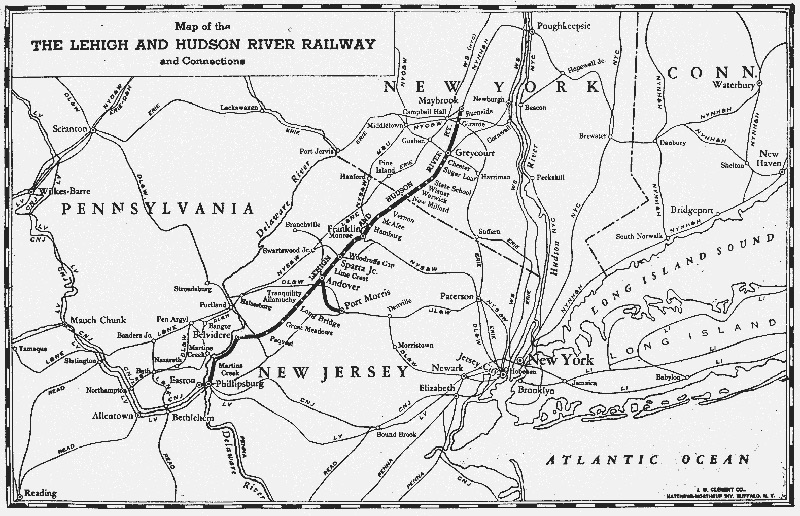
The Lehigh & Western in a 2nd-floor room features a single-track folded dog-bone layout with an automatic block control system. Three trains can run simultaneously and the two on the 150-foot main will run and pass automatically according to the route levers program. The layout includes lighted buildings, street/yard lights, flashing water tower lights, animated billboards, caboose/passenger cars constant-brightness lights, and sound effects that accent the layout scene. A 27-inch computer monitor shows the animated model railroad activity controlled with wireless or tethered throttles. The Lehigh & Western’s prototype area is the Lehigh and Hudson River Railway that ran from Easton, PA to Maybrook, N.Y .
LAYOUT
• Prototype area is the Lehigh & Hudson River RR running from Easton, PA to Maybrook, NY through northwestern New Jersey; see map below. The era is 1930’s to 1950’s.
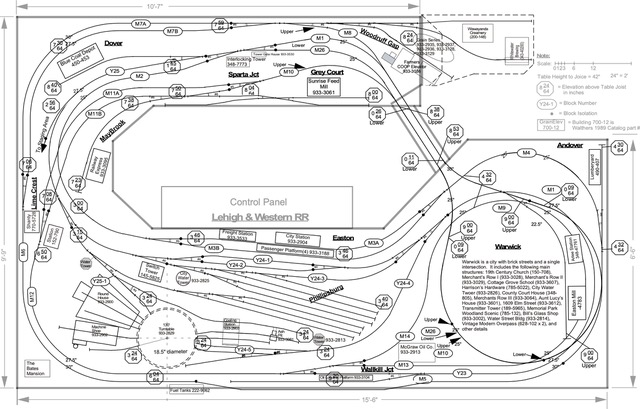
• The layout is 15.5 feet by 9.75 feet, L-girder table construction, no nails, and thousands of #8 1-1/4 inch screws. The room is about 12 by 18-foot and the layout can be walked around on two sides. All points are accessible without climbing over the layout. The roadbed is cork over ½” homosote supported with risers from the L-girder structure. Control panel is in the middle and accessible via a stoop-under bridge. The scenery is 100% complete. See the L&W Track schematic below.
• The layout consists of 437 feet of Shinohara code 70 HO track and 44 turnouts (#6) controlled by twin-coil switch machines. The mainline run is 150 feet with a 250-foot round-trip run. The mainline curves are 25-inch minimum radius and all are eased for smooth entrances and exits.
• The single track mainline with three passing sidings is arranged as a “folded dog bone” and includes two reversing loops. Ten towns/cities are arranged along the main and yard with 11 spurs, a passenger terminal siding, and a large yard in Phillipsburg. The grades are a maximum of 1 3/4 percent.Light operational sessions have been completed with switch lists using JMRI Decoder Pro software.
• The Phillipsburg yard includes eight freight spurs, one engine spur, three track runarounds, 130-foot turntable with 3-stall roundhouse, 1-stall machine shop, three maintenance spurs, and three entrances to yard. The yard also includes three 9-1/2 foot staging spurs with a 10-foot lead-in. These staging spurs are hidden from normal view, infrared detectors and a video camera allow the operator to fully monitor activity on these hidden spurs. The yard is accessible via two entrances on the mainline, one at Sparta Jct and the other at Wallkill Jct. The yard can be used as a short cut between the reversing loops on the mainline (Sparta Jct to Wallkill Jct 33 feet via the yard versus 120 feet via the mainline). The linked Sparta Jct yard has four freight spurs with a total capacity of 24 cars. This yard is hidden from normal view, infrared detectors and a video camera allow the operator to fully monitor activity in this hidden yard.


CONTROL SYSTEM
• The control system is an automatic block control system. The mainline consists of 13 blocks in each direction for a total of 26 blocks. The yard has 3 blocks; one of these blocks actually skips 11 of the regular 13 blocks. There are three walk-around CAB controllers (A, B, & C); therefore, three trains can be run simultaneously. The mainline control panel is a series of route levers. One set for CAB A and the other for CAB B. Within each set are two groups of route levers. One group for westbound and the other for eastbound. All mainline switch machines are controller by the route levers and at the time when the train approaches the switch.
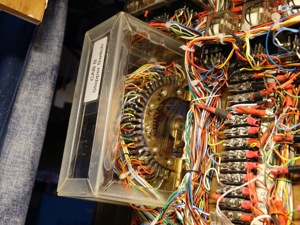
• The heart of the control system is two 26-postion 8-pole stepper switches, one for CAB A and the other for CAB B. Also, at the heart of the control system is 70 4-pole double throw relays. The control system knows where each train is at all times. Only CAB A & B can run on the mainline. CAB C can only run in the yard plus either CAB A or CAB B can run in the yard as a Road CAB at any one time. The Yard CAB can be declared as CAB A, B, or C; normally it is CAB C. Therefore, two trains can run on the main or two trains can run in the yard. Each section of track in the yard includes a toggle that selects: Road CAB, OFF, or Yard CAB. With these toggles two adjacent yard tracks can have engines controlled from two different CABs. These toggles allow one to transfer control from one CAB to another.
• The stepper switches automatically step when a train clears a rear block.

The control system knows when a train clears a rear block by sensing an absence of current in that block. Each car has one resistive (5,000 ohm) wheel axel except those that have interior lights. There are always two blocks powered by a CAB at any one time (the middle block and the rear block). The control system looks in the forward block for voltage or current. If it senses voltage or current then there is a possible collision ahead and red lights plus audio alarm alerting the operator of a problem.
• Either train operating on the main line can operate as a “Long Train” or a “Normal Train”. A “Normal” length train is restricted to about one mainline block long or about 8 feet. A “Long” length train can be up to twice as long or about 16 feet. The control system is designed for up to three operators; however, because of the small space it would be awkward for more than two operators to be present.
• Each of the tethered walk-around CAB controllers are custom designed and include: pulse width/DC modulation, two level of momentum, two levels of breaking, CAT 5 coiled connecting cable, Forward- OFF-Reverse Toggle, sound button, full throttle limit trim adjust, minimum throttle limit trim adjust, meter with voltage or current selection, 16 volts at 0.75 Ampere with overload light and over current protection, and remote breaking from control system. Each CAB controller unit is identical and auxiliary jacks are available on the backside of the layout for troubleshooting. Each controller can be unplugged and moved to another jack while keeping the engine it controls coasting and continuing on its journey uninterrupted. The operator has the option to use the tethered or his iPhone/iPod as a wireless throttle.
• Because the mainline is a “dog bone” there is a great challenge to operate two trains simultaneously. The three passing sidings are used for trains to pass each other. One train waits on the passing siding with full sound capability while the other train speeds by. Also, the yard and one of the reversing loops can serve as a passing siding. The passing siding in the middle of the main (block 7) provides a mode for running two trains simultaneously on the main fully automatically. When in this mode the train controlled by CAB A automatically stops and starts waiting for the train controlled by CAB B to pass. This stopping and starting uses the remote braking feature of the CAB controller. When the CAB A train stops it still has full sound capability. When two trains run automatically on the main a single operator can turn his attention to running a third train via CAB C in the yard
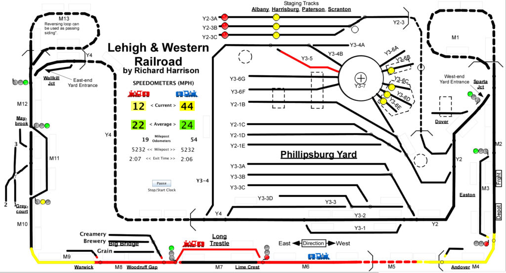
• A 27-inch computer monitor hung on the ceiling above the layout displays, in an animated fashion, the location and direction of the trains, the powered track blocks, the states of the block signals, the position of the turnouts, and the state of the infrared detectors that monitor hidden tracks. A Macintosh computer runs JMRI Panel Pro with extensive LOGIX equations. A LocoNet buffer and custom interface electronics provides the interface for 168 signals coming from the main terminal board. See below for an example of the displayed image.
• The control system is fully documented with schematics. It is very maintainable because all nodes go to a terminal board. I re-program the system by moving wires and/or adding diodes. I am a retired electronic engineer and find the control system my “cup of tea”.

OTHER FEATURES
• There is an Auto-Run Yard Cab mode available, strictly for show. The Yard Cab can run a short train back and forth through the Phillipsburg Yard, including into two different yard spurs, totally automatically without operator intervention. This allows a single operator to have a train operating in the yard while two other trains are operating on the main line.
• Lighting and sound effects are amongst the Lehigh and Western’s highlighted features. All buildings are light with the lighting from the top; baffles are carefully placed so that one cannot look through the building, nor see the light fixture. Several animated signs, lighted billboards, and flashing water towers create a special appeal to the observer. My passenger cars and several cabooses have lights with individual car regulators so the light brightness is independent of track voltage.
• There are several sound effects around the layout that automatically produces sound that is appropriate for the scene. These include: Easton railroad station, church bell, railroad crossing bell, sawmill, conveyor, mine blast with light flash, welding operation, and turntable. There is an ambient sound effects which includes lightning (flashing overhead) and thunder which can be activated as a single event or continuously at random. Other sound effects will be added in the future.